Fiber Optic Fire Alarm Network Diagram
Free Printable Fiber Optic Fire Alarm Network Diagram

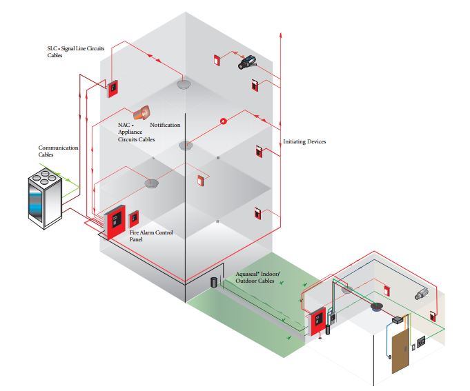
Riser diagram and wire pull for some commonly used fire alarm circuits.
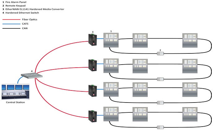
Fiber optic fire alarm network diagram. Rs 232 rs 485 20 ma fiber optic 2 phone 1 low level audio 1 25 vrms audio 70 vrms audio 4 24 vdc control circuits 2 120 vac control. If using single mode use the smxlo or smxhi. You don t have to manually do cost estimations any longer. Connecting fire alarms the easy way apartment buildings strip malls and other multi building applications were monitored individually in the past.
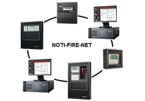
Noti fire net is the interface which allows notifier intelligent fire alarm control panels to form a network. Refer to data sheet s4100 0057 for details. Sfo fiber optic cable characteristics and requirement are available in appendix b. The local side of a wiring link has direct non isolated electrical connection to the head end cabinet.
Open or closed network operation. The installation of fire alarm system wiring is similar in many respects to any. Terms are continued next page 2 s4100 0049 11 5 2018 4120 network fiber modems for internal mounting in fire alarm control panels not ulc listed. Fiber optic multi mode wire or combination wire fiber communications path.
3 fibmb class b network and audio fiber optic connections 3 cpu class a network and audio fiber optic. Based on proven arcnet technology. Fiber optic modem in the communications path. Fire alarm network communications wired or fiber optic physical bridge modules connect multiple network loops and provide star topology connections physical bridge modules connect to network communications using wired or fiber optic media and interconnect using modem media modules.
As well as it auto generates the rack diagram wiring log book 3d view bill of materials and specification with project costs. The following wiring diagrams can be used with single or mul timode fiber. Optical fire and security can provide a fast efficient network solution to help you connect with your clients and workforce. A common way of consolidating the central station communications was running a signaling line circuit slc between a main panel and remote panels in different buildings.
Network design tool automatically calculates the lengths of cables conduits trays trunks pipes etc. The proposed sfo campus fire alarm network segmentation diagram is available in appendix c. The existing sfo fire alarm nodes and their device breakdown as of december 2014 is available in appendix a. Est3 multiplexed fire alarm system standard features class a or class b style 7 or style 4 network data connections.
Each local control panel network node maintains its own area of protection while monitoring and controlling other areas other network nodes.


