Hsrp Network Diagram With 3 Swi
Free Printable Hsrp Network Diagram With 3 Swi

Interface fe0 1 on rtr a will have a physical ip address 10 10 10 1 and interface fe0 1 on rtr b will have a physical ip address 10 10 10 2.
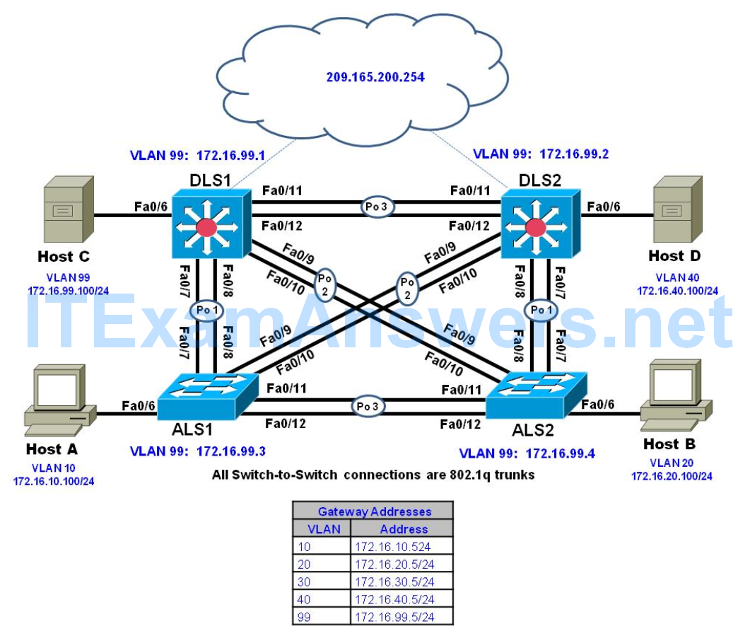
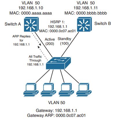
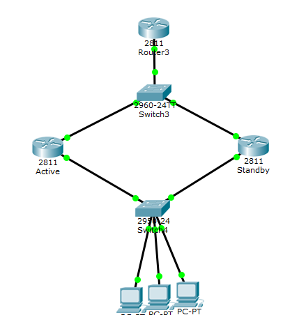
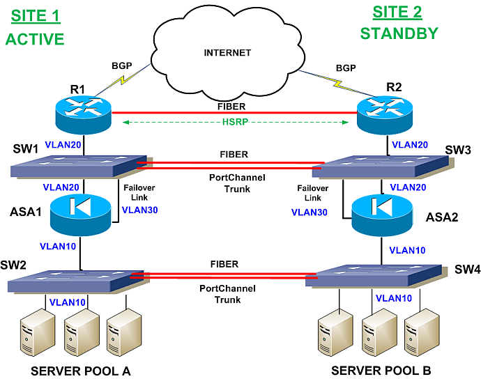
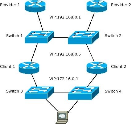
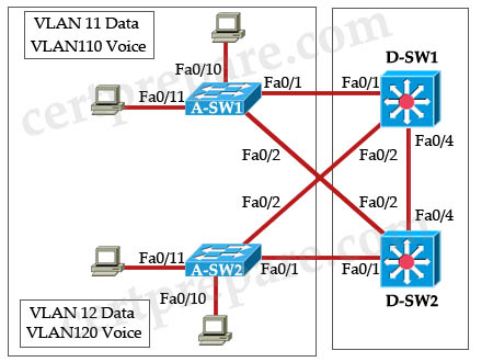
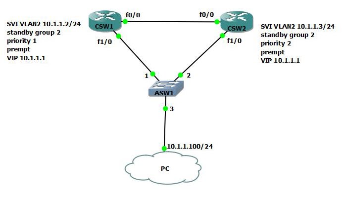
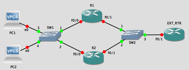
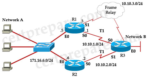
Hsrp network diagram with 3 swi. For our example let s add pc2 to the lab setup. When you run the hot standby router protocol hsrp between two routers connected via a lan switch you may observe instability in hsrp. A cisco network diagram showing hsrp. The network diagram below shows two pes with hsrp running between their vpn routing forwarding vrf interfaces.
The standby group number the default is 0. Hot standby routing protocol or hsrp is a cisco proprietary protocol that allows two or more routers to work together to represent a single ip address for a particular network. This document explains why this instability occurs and how you can avoid it. Network diagram for hsrp and ip sla service level agreements with additional features of boolean object tracking edge router 1.
Therefore you can configure only three hsrp groups on token ring interfaces unless you configure the standby use bia parameter. This is the basis of hsrp. Track 4 ip sla 1. This often happens during a network disruption or an active router transition such as an hsrp router with a higher priority and preempt configured being added to the lan.
An hsrp address 10 10 10 3 will be also configured on both routers. A hello packet is sent every 3 seconds by default. Hsrp version 1 uses the mac address range 0000 0c07 acxx while hsrp version 2 uses the mac address range 0000 0c9f f0xx where xx is the hexadecimal number of hsrp group. Hsrp as well as virtual route redundancy protocol vrrp are considered high availability network services that allow for almost immediate fail over to a secondary.
Hsrp peer routers that protect a subnet are able to provide access to all other subnets in the network. We configured the ce with the hsrp virtual ip address as its default route. Track 5 ip sla 2. Created two track objects track 4 and track 5 with slas tracker and both track objects called in track 6 object with boolean or condition.
Track 6 list boolean or object 4 object 5. For explanation sake we will call hsrp group 1 network one and hsrp group 2 network two. You can edit this cisco network diagram using creately diagramming tool and include in your report presentation website. R1 will be active for network one while r2 will be active for network two.
And we configured hsrp to track the interfaces connecting the pes to the rest of the provider network. From the diagram above hsrp will be running between interfaces fe0 1 on the two lan routers. The group numbers of hsrp version 1 range from 0 to 255. Therefore which router becomes the active hsrp router is irrelevant.
If you are configuring hsrp on vlan trunks each vlan or ethernet sub interface must be in a different standby group. The hold time dead interval is 10 seconds.

