Network Diagram A And B No Predecessor
Free Printable Network Diagram A And B No Predecessor

Although some tasks have to be performed in a specific order others don t.
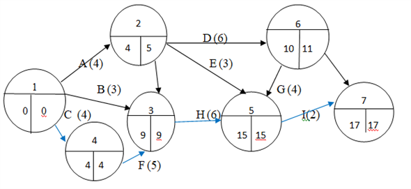
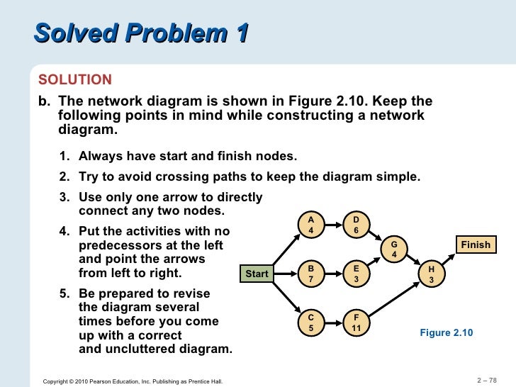
Network diagram a and b no predecessor. It is a subdivision or a part of a complete project network diagram. Then we have the following representation for a. Develop a network diagram for the project specified below. It s very simple straightforward.
Activity b is a predecessor activity that logically comes before a dependent activity f in this network system. After you ve switched views you can add a legend customize how your boxes appear and print your network diagram. This video is unavailable. For example activity i j is predecessor activity j k j l in the network diagram shown in fig.
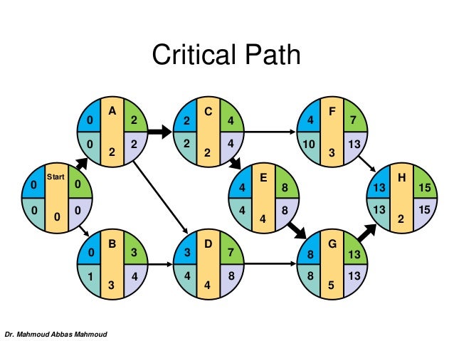
I would draw then activity a and then we have activity b. The es for e is the greatest ef of its predecessor activities b and c. The duration 5 17 work days is added to the es to get an ef. The figure drawn below depicts a sample project.
Activity immediate predecessor activity a b a c d b e c f d g e f solution activity a has no predecessor activity. Activity f is a successor activity a dependent activity that inevitably occurs after the activity f. Let us suppose that activity a takes the project from event 1 to event 2. And then we have activity c.
Project network diagram example. Construct a pdm network diagram whe. C is the predecessor of it is a. Activity d the predecessor activities for d is b and c.
It is an activity which must be completed before particular activity start. There are two types of network diagrams activity on arrow and. To draw your project s network diagram you first have to decide the order of your project s activities and that means setting precedence. Sub network it is simply called as a subnet.
A network diagram can be created by hand or by using diagram software. Similarly a predecessor can have more than one successors. A predecessor to an activity is an activity or milestone that determines when work on activity a can begin. The rest is pretty straightforward.
Boxes or nodes represent tasks and dependencies show up as lines that connect those boxes. A network diagram is a graphical way to view tasks dependencies and the critical path of your project. Since b has an ef of 5 33 and c has an ef of 9 17 the es of e is 9 17. There is an f s relationship between activity b and f.
Dependencies a successor dependent node can have more than one predecessors. Activity b the predecessor is a. And we said the relationship between activity a and b is a is the predecessor. Then it is known as predecessor activity to that particular activity.
Skip navigation sign in. After adding all the activities to the diagram draw a box to represent end and draw an arrow from activity 4 the last activity you have to complete to.


