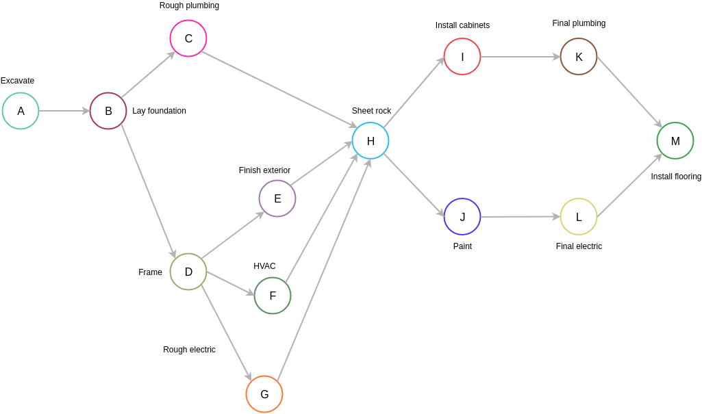
Network Diagram Aon Format
Free Printable Network Diagram Aon Format

Aon diagrams are generally easier to create that aoa diagrams.
Network diagram aon format. Project network diagrams aoa aon a project network illustrates the relationships between activities tasks in the project. These diagrams are used for cpm critical path method and pert program evaluation and review technique which help to optimize the performance of tasks in a project. Tt and ff indicate where to place float values. Showing the activities as nodes or on arrows between event nodes are two main ways to draw those relationships.
Activity on node is a project management term that refers to a precedence diagramming method which uses boxes to denote schedule activities. After you ve switched views you can add a legend customize how your boxes appear and print your network diagram. An aoa network diagram or activity on arrow network diagram uses circles and arrows. In this episode i continue drawing network diagram using aon or pdm notation.
Sandeep kumar gour 63 113 views. Aon diagram you can edit this template and create your own diagram creately diagrams can be exported and added to word ppt powerpoint excel visio or any other document. A network diagram is a graphical way to view tasks dependencies and the critical path of your project. When it comes to inexperienced users aon diagrams is easier to understand than aoa diagrams.
To find the network diagram view choose view network diagram. Network diagram activity on node and activity on arrow in pert and cpm aoa and aon hindi duration. You find out how to draw the network diagram for a sample project from the information in. Use pdf export for high quality prints and svg export for large sharp images or embed your diagrams anywhere with the creately viewer.
Boxes or nodes represent tasks and dependencies show up as lines that connect those boxes. Here s a simple example that can help you learn how network diagrams can be useful in any project you manage. Once all activities are arranged in logical order and relationships are set the logic diagram is ready for the calculation process. Creating a network diagram can be an involved process that begins after you ve determined predecessors to your activity.
Arrows represent activities and the circles are nodes representing the start and finish points of these activities. In another episode i will show how to calculate starting. These various boxes or nodes are connected from beginning to end with arrows to depict a logical progression of the dependencies between the schedule activities. The format used to indicate values for each activity is shown in exhibit 2.


