Network Diagram Lead Time
Free Printable Network Diagram Lead Time

If the said fs relationship was without any lead the project team would have needed 5 days.
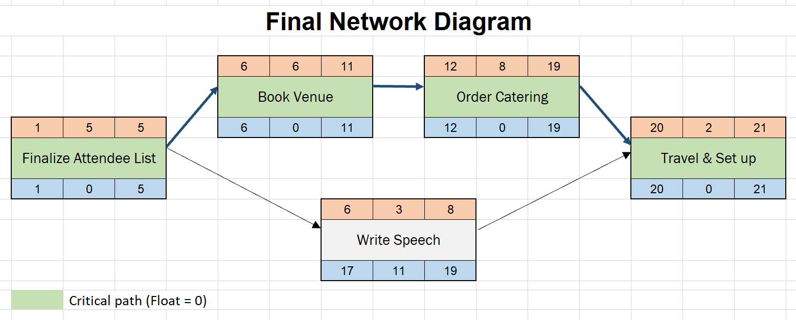
Network diagram lead time. If you are not yet familiar with this technique read this introduction to lags and leads that also comes with an illustrated example. Project network diagram representation of lead in our example the project team would need 4 days to complete these activities. So we can meet the deadlines. Although the concept is easy a few people still find it difficult to understand.
Lead in network diagram helps in achieving that. In this blog post i will explain lead time and lag time with simple real world examples. Lag lead compensating network now let us determine transfer function for the given network and the transfer function can be determined by finding the ratio of the output voltage to the input voltage. What is lead and lag time.
Lead vs lag lead time lag time in scheduling. When the first activity finishes a second activity starts. While creating a work schedule or a network diagram professionals often use many terminologies such as lead time lag time total float free float etc these scheduling tools are used along with activity relationships in order to model the real nature of work to be performed. Network is a graph showing each activity to be performed its predecessor.
Project network diagrams are not exclusion. The successor has therefore a lead time of 2 days. There are people who simply do not see the necessity of network diagrams. Lead time project scheduling is often the most visible step in the sequence of steps of project management.
The most common method for creating a network diagram is precedence diagramming method which is abbreviated as pdm. There can also be errors when making it or other factors that can influence. Lead time and lag time both play an important role in network diagram development. Given below is the circuit diagram for the phase lag lead compensation network.
Lead time is the amount of time whereby a successor activity can be advanced. When sequencing the activities the relationships and dependencies between the activities should be kept in mind. During sequence activities process which is the third process of time management the activities of a project are sequenced and a network diagram is created. Fig i network analysis diagram network representation of a project project and activities are represented by a network.
For more details on lead and lag with practical examples simple watch following video. You can draw the gantt chart without doing a network diagram and many people do i have as well. Hence the network diagram calculates the critical path behind the scenes and gives the project manager the knowledge they need to ensure the project finishes on time and budget. Transferring this into a project schedule network diagram leads to the following result.
Creating and understanding the project schedule network diagram.


