Rj31 Wiring To Network Interface Wiring Diagram
Free Printable Rj31 Wiring To Network Interface Wiring Diagram

Telephone Master Socket Wiring Diagram
Rj31x Jack Diagram Wiring Diagram Images

Telephone Master Socket Wiring Diagram

Rj 31 Jack Wiring C3 Wiring Diagram

Rj31x Google Search Diy Bricolage

Hai 20a00 8 Omnipro Ii Controller For Structured Wiring By Hai
Wiring a telephone junction box diagram new wiring diagram for phone rj12 telephone wiring diagram australia new phone jack wiring.
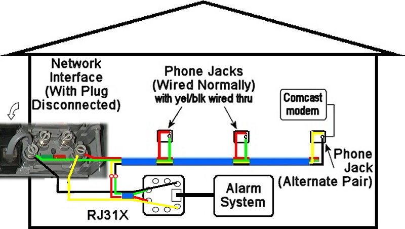
Rj31 wiring to network interface wiring diagram. Blue blue green green should work. Variety of telephone network interface wiring diagram. Network 8 position usoc rj31 x or rj38 x jack 8 pin modular phone cord to local. This will insure compliance with ethernet wiring standards.
The rj38x jacks are almost identical to other usoc registered jack rj31x also used for fire alarm and security equipment connections. The network interface device nid links the telephone network to the telephone wiring inside your home. Only 4 conductors are used. Rj31x jack wiring purpose is to allow the alarm system to seize the line and dial out even when the phone is off the hook wiring a rj31x jack for a home alarm system september 02 a rj31x is nothing more than a specially wired rj45 plug that allows a security system to share the telephone line with standard household phones instead of paying.
Outdoor nids are usually located on the outside wall centurylink nid wiring diagram dsl efcaviation of white wire telephone jack wiring diagram dec 20 from top to bottom. There will already be a wire coming from the alarm system the rj31x jack with two pairs being used the orange pair which feeds the phone jacks inside the home from the alarm the yellow and black pair in this diagram and the blue pair which carries dial tone to the alarm from the network interface box the red and green pair in this diagram. Click on the image to enlarge and then save it to your computer by right clicking on the image. Plug the line and phone plugs into the appropriate jacks on the pers console.
Wiring the cat 5 cable is a bit tricky since you have to wire the 1st line blue pair into the relay and wire the 2nd line orange pair out. The jack should have a wiring diagram or designated pin numbers colors to match up to the color code below. When wiring a jack or an rj 45 plug remember to keep the twist as close as possible to the jack or plug receptacle. A single ended 8 conductor modular line cord is used to connect the pers console to the telephone jack.
Telephone network interface wiring diagram building electrical wiring layouts show the approximate places and also affiliations of receptacles lighting and irreversible electric services in a structure. Like rj31x this wiring provides a series tip and ring connection through the connecting block but is used when the customer premises equipment is connected in series with a single station such as an automatic dialer. The difference is in the short strap connection between pins 2 and 7 that lets the equipment specifically designed to be plugged into a rj38x jack to probe if it has beet attached to the correct jack type. It also seems a little strange to have one cable supporting both the input line and.
Rj31x adapter for use with the pers consoles. Your patch panel may already have an rj31x jack and save you the trouble of wiring one up. Of the telephone jack wiring.

Lf 5902 Tip Ring Telephone Wire Diagram Free Diagram
General Connecting A Line Seizure Jack

Hai 20a00 52 Omni Iie Controller For Structured Wiring Enclosures

Vonage Forum Home Wiring And Installation Page Two

Telephone Master Socket Wiring Diagram

Ademco Honeywell Vista 21ip Pcb Board Version 3 13 By Honeywell

Telephone Master Socket Wiring Diagram
Isdn Tutorial Interfaces

Syba Sata Ii Pci X 4 Ports Host Raid Controller Card By Syba

Telephone Master Socket Wiring Diagram

Voice Data Fax World Modem V92 Universal Pci By Multi Tech Systems

Monster Beats Headphones Extension Cable 3 5 Extension Cable By

Pin On Satellite Tv Receiver

