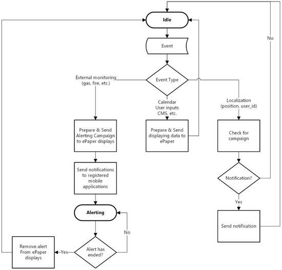
Sink Node Network Logic Diagram
Free Printable Sink Node Network Logic Diagram

User Registration Process Flow Diagram User Registration Process

Activity On Node Project Management Knowledge

Pin Di Diagram Alimb For Us
Sensors Free Full Text A New Data Fusion Algorithm For

Lora A Secured Gateway With Low Power And Rates Power Radio

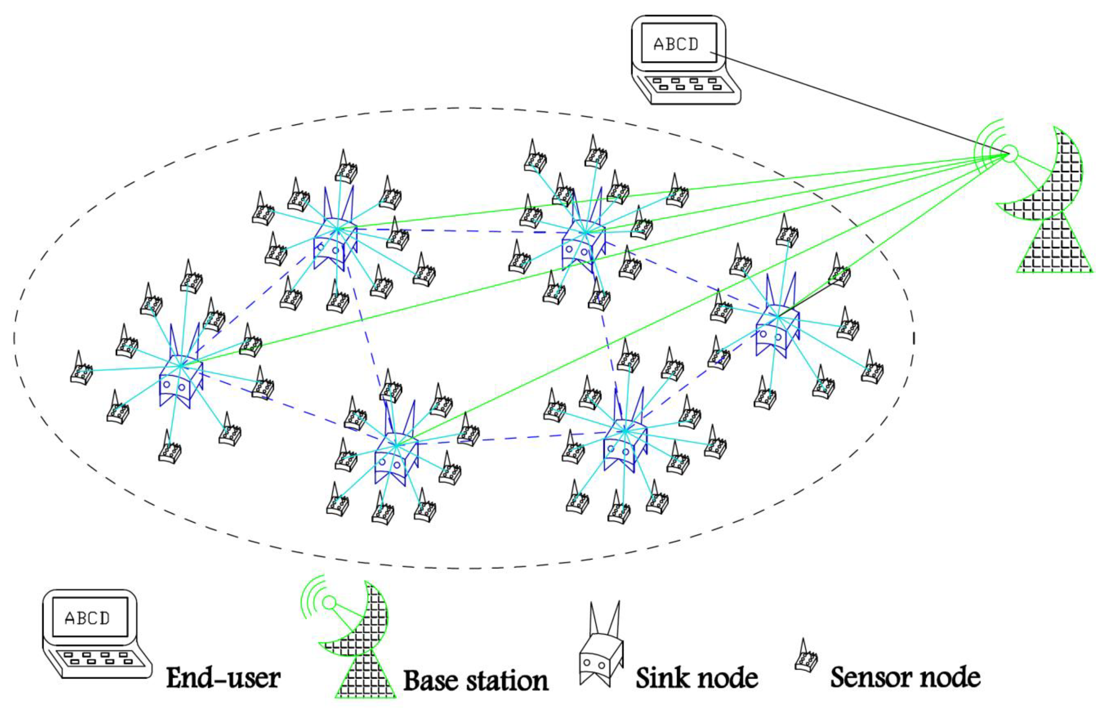
Shows The Wireless Sensor Network Architecture That Is Applied In

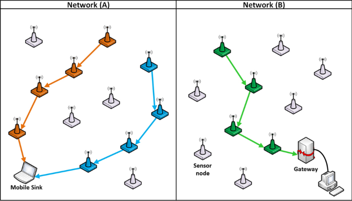
The sink can be a gateway between the wsn and other king of networks.
Sink node network logic diagram. All nodes from the same nutanix cluster. A physical topology details how devices are physically connected. Nodes in a network logic diagram which have multiple predecessors. Next read how to construct a precedence diagram given a list of activities.
Do not mix network physical adapters with different speeds 10gbps and 1gbps or 10gbps and 40gbps and so on in the virtual bridge. Often in operations research a directed graph is called a network the vertices are called nodes and the edges are called arcs a flow must satisfy the restriction that. A network topology map is a map that allows an administrator to see the physical network layout of connected devices. Logical and physical topologies can both be represented as visual diagrams.
To emphasize that flow conservation still holds at source and sink nodes a dashed phantom arc can be shown on the network diagram. In a network diagram the start of an activity must be linked to the end of another activity. The amount of flow on an edge cannot exceed the capacity of the edge. See the examples in figures 10 1 b and 10 1 c.
Network diagrams in project management are a visual representation of a project s schedule. The sink is the common destination of all data collected by nodes in the network in case of convergecast data profile. Note the nodes that are not connected are summary tasks. What are network diagrams.
Br0 up network logical bond with physical nic s attached. A network diagram in project management is useful for planning and tracking the project from beginning to finish. Nodes in a decision tree showing various branches with the same chance. Ethx physical network adapter enumeration.
In graph theory a flow network also known as a transportation network is a directed graph where each edge has a capacity and each edge receives a flow. Whether a coin flip comes up heads or tails each branch represents the outcome of the test and each leaf node represents a class label decision taken after computing all attributes the paths from root to leaf represent classification rules. Now we use a. To display a network diagram of the schedule select the task tab view ribbon group gantt chart drop down menu and network diagram figure 2.
The network diagram for our demonstration project is displayed in figure 3. A logical network topology is a conceptual representation of how devices operate at particular layers of abstraction. Node or a net loss of flow out of the network sink node. For example kill points are milestones.
A decision tree is a flowchart like structure in which each internal node represents a test on an attribute e g. Nodes in a conditional network diagram at which it becomes deterministic. A network diagram will always have the start and end events. They may also have other events called milestones.

Logic Diagram Of A 3 Bit Counter Design Download Scientific Diagram

Plc Programming Basics Using Ladder Logic Plc Programming Learn

Network Logical Diagrams A Flow Diagram Of A Ffd Coordinator B

Revised Stm32 Blue Pill Pinout Diagram Elektronika

Logic Diagram Of The 3 Stage Decoder Download Scientific Diagram

Logical Diagram Of Layer 2 Entities And Interfaces To Layer 1

Plc Trainer Free Download Teknoloji Egitim

Decreasing Sine Wave Amplitude Grasshopper Sine Wave
Sensors Special Issue Green Communications And Networking For Iot

From The Ceo S Desk Devops Maturity Assessment A Navigator On

Precedence Diagramming Method Activity On Node Method In

Pin By Puru Kathuria On Digital Logic Logic Math Diagram
Pin On Technology