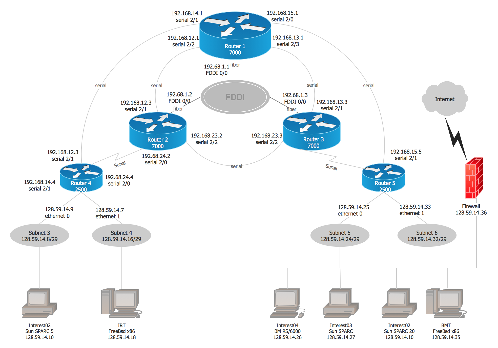
The Physical Logical Network Diagram Wi
Free Printable The Physical Logical Network Diagram Wi

A logical network is a virtual representation of a network that appears to the user as an entirely separate and self contained network even though it might physically be only a portion of a larger network or a local area network.
The physical logical network diagram wi. Draw a logical diagram for the entire 64 96 132 0 22 network. There are two types of network diagramming logical and physical. Multiple physical networks can support one big virtual one or vice versa a single modem with all its cables and everything involved can establish. Net1 needs to support 190 hosts but may later grow to.
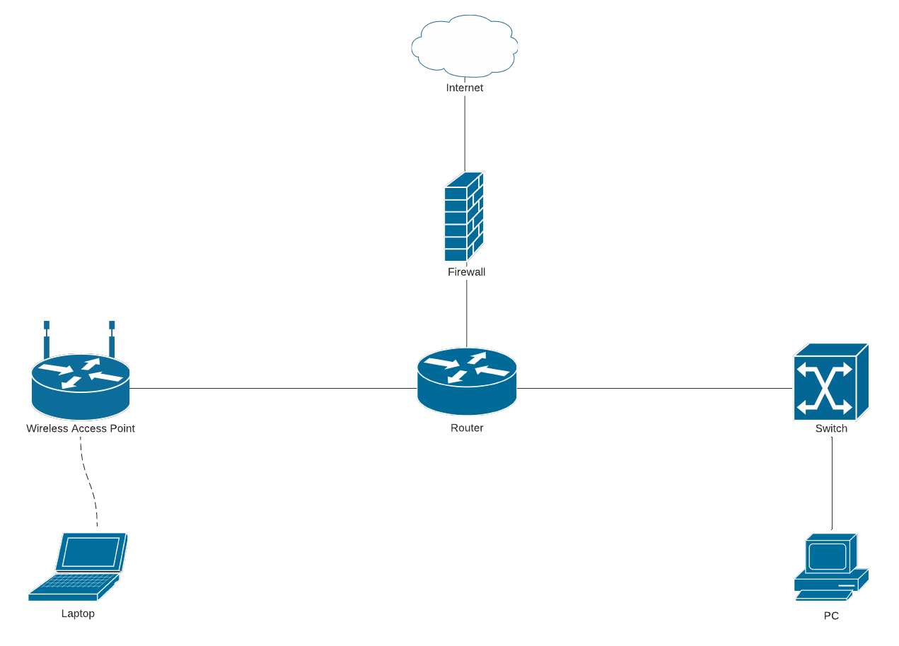
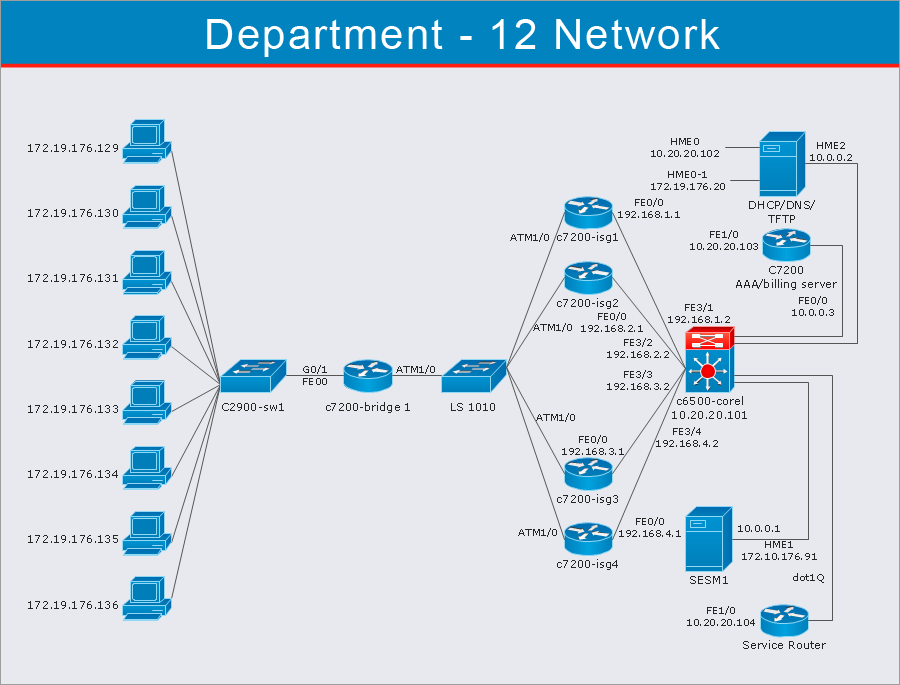
Logical network diagrams focus in on how traffic flows across the network ip addresses admin domains how domains are routed control points and so on. A logical network diagram usually shows network devices like routers firewalls and voice gateways. Ip structure is a big part of the logical design of a network as well as security planning. Therefore it s essential to understand the differences so you can choose the right kind of mapping for each aspect of your organization.
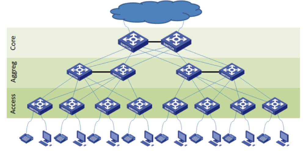
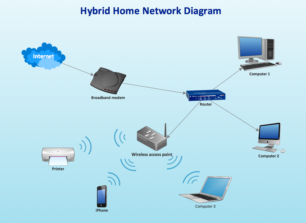
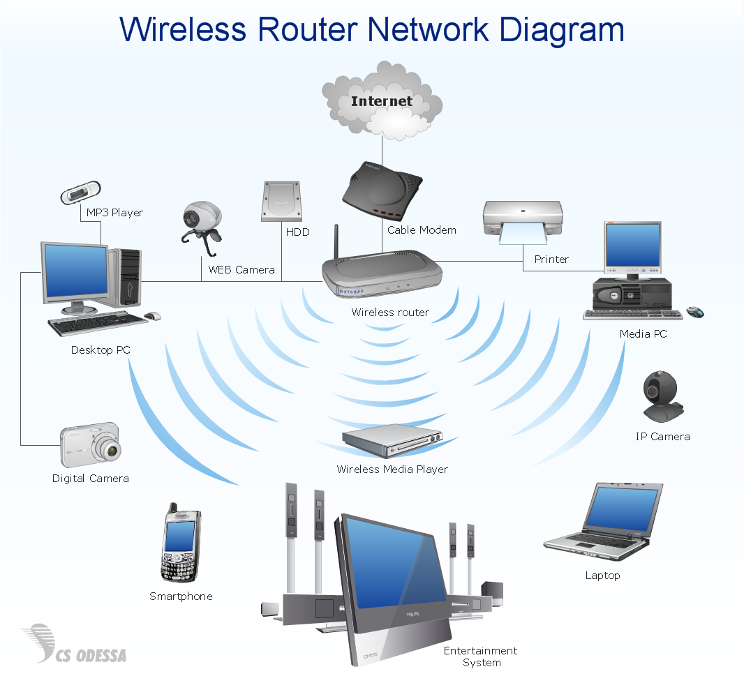
A network diagram is a visual representation of a computer or telecommunications network. With up to date diagrams network admins can troubleshoot and minimize downtime plan for capacity avoid it clutter maintain software and keep the network secure and compliant there are two main types of network diagrams. A physical network is the sum of the physical hardware parts that make up a network including cables and routers this is unrelated to the virtual logical network that users see when they log into their computers and check the networks tab. It might also be an entity that has been created out of multiple separate networks and made to.
The logical network topology can be inferred from the network diagram if details of the network protocols in use are also given. It shows subnets vlan ids subnet masks and ip addresses. You will draw a physical and logical diagram for a network which is 64 96 132 0 22 we have 3 internal subnets. Physical network diagrams.
A logical network diagram illustrates the flow of information through a network and shows. Network diagrams both logical and physical are key to effective network and it infrastructure management. Within the osi model of networking logical diagrams are referred to as l2. Thus giving us the true meaning of the term logical.
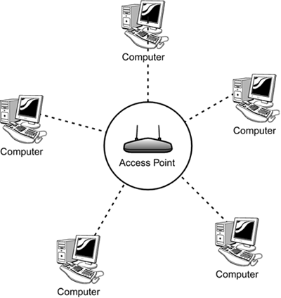
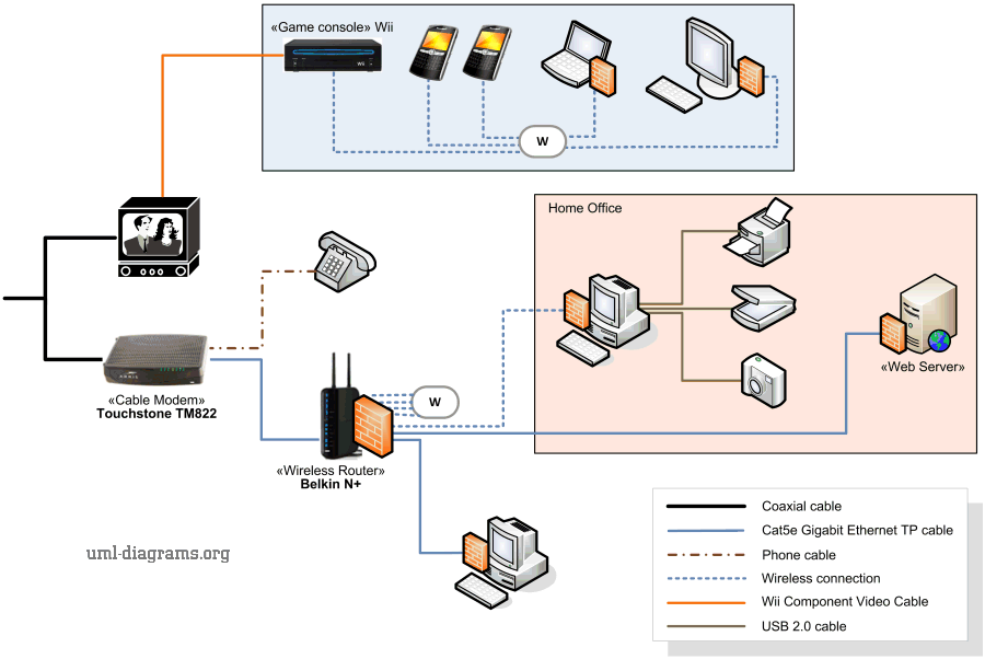
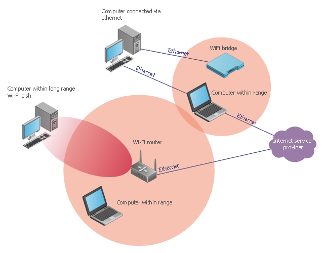
In the logical design we usually do not show the actual interfaces and physical cables in the diagrams. The physical network topology can be directly represented in a network diagram as it is simply the physical graph represented by the diagrams with network nodes as vertices and connections as undirected or direct edges depending on the type of connection. The two most common network diagrams you ll come across are physical and logical. This network diagram shows a local area network lan.

