Transmission Line Sequence Network Diagram
Free Printable Transmission Line Sequence Network Diagram

Electricity Power Network Isometric Flowchart Vector Image On In

Tracemodeler Com

22 Great Ideas Of Template For Network Diagram Design Diagram

Smart City Mesh Networking Wireless Mesh Network Technology

Drawing Activity Diagram With Visual Paradigm Www Visual

Sequence Diagram Network Configuration And An Example

Figure 8 shows the one line diagram of a generator g feeding a motor m through a two section transmission line.
Transmission line sequence network diagram. Z1 z2 j?? l m 41 z0 j?? l 2m 42 so in analysis of networks with transmission lines it is now possible to replace the lines with three independent single phase networks. To calculate the sequence voltage changes throughout the pps nps and zps sequence networks using their nodal impedance matrices we need to calculate the equivalent sequence currents to be injected at nodes j and k in each sequence network. Assume that the base values in the region of transmission lines are 100mva 345kv. Gm l1 l2 r 0 figure 1 system one line diagram.
In figure 1 c s. Transmission line is bilateral an interconnected transmission network is not bilateral due to the dispersion of active components generators throughout the network. Because of a transmission line s passive and bilateral properties the phase sequence of the applied voltage makes no difference as b c positive sequence voltagesa. Using these complete sequence networks of a power system can be easily drawn.
Figure 1 single line diagram of transmission and distribution network. The voltage is then stepped up by suitable 3 phase transformers for transmission purposes. These are easily calculated from figure 6 24 by replacing each sequence voltage v x in series with the circuit impedance z x x p n or z with a. Central station where power is generated by 3 phase alternators.
The positive negative and zero sequence impedances of the balanced transmission line are then. Represents the central station where power is generated by 3 phase alternators at 6 6kv or 11kv or 13 2kv or even 32 kv. Neutral and or earth is so much greater than for positive and negative sequence currents which return balance. In fact the single line reactance diagram as employed for calculation of symmetrical fault current is the positive sequence diagram of the power system.
On the given bases the transmission line sequence reactances are x x 10 x 30. This is because the spacing between the go and return i e. Figure 9 shows the positive negative and zero sequence networks of the system. The zero sequence network must therefore have a path from the line h on the star side through the zero sequence impedance of the transformer to the reference bus while an open circuit must exist on the line l side of delta see fig.
The reactance of transmission lines of zero sequence currents can be about 3 to 5 times the positive sequence current the lighter value being for lines without earth wires. If the star neutral is. The generator is resistance grounded through resistor r0 while the motor remains ungrounded. The positive sequence network is drawn by examining one line diagram of the power system.

Uml Create New Customer Sequence Diagram With Images Sequence

Creating Swimlane Activity Diagram Using Visual Paradigm Uml Tool

Iptables Processing Flowchart Updated Often Flow Chart

Osi 7 Layer Model Osi Model Osi Layer Network Layer

25 Activity On Arrow Network Diagram Examples Samples Diagram

Network Diagram Networking Basics Computer Network Computer

Dc Motor Control Circuit Diagram Schaltplan Elektrotechnik

Complementary Control Valve Sequence Control Valves Valve

H Framers Transmission Line Power Wind Turbine
25 Auto Network Diagram 101 References Diagram Design Diagram

21 Clever Home Wiring Diagram Software Free Design Electrical
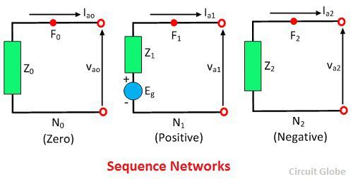
What Are Sequence Networks Definition Explanation Circuit Globe

Gpon Upstream Transmission In The Upstream Direction Each Onu Can

